5mm Red LEDs Electronic DIY Kit(NE555)
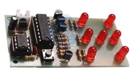
Electronic dice kit is based on the NE555 oscillator circuit and fun circuit CD4017 counter display kit. Can simulate the dice, make fun of the game.
1. Kit parameters:
Supply voltage: 4.5-5V
Dimensions: 74 * 35mm
2. Function play:
When a power-up, 7 LED will randomly display a number of points, players press the switch S1,7 all lit LED only after about 7 seconds LED light starts blinking, until finally showed stable points. Throughout the end of the first “crap” process.
circuit mainly by the pulse generator and a decade counter circuit. Pulse generator and external elements by NE555 multivibrator, when you press the button S1 when Q1 turns on, the output pulse NE555 3 feet, then five turns the output CD4017 output high, resistors and transistors by different combination, can drive seven LED light to indicate the number of points 1-6 points.
4.Circuit diagram:
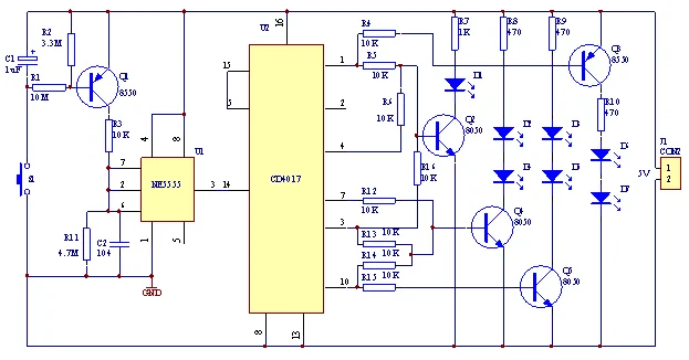
5.Component list:
| serial number | Component | Value | Label | serial number | Component | Value | Label |
| 01 | resistance | 470R | R8 R9 R10 | 11 | audion | S8050 | Q2 Q4 Q5 |
| 02 | 1K | R7 | 12 | S8550 | Q1 Q3 | ||
| 03 | 10K | R3–R6 R12–R16 | 13 | IC socket | 8PIN | U1 | |
| 04 | 3.3M | R2 | 14 | 16PIN | U2 | ||
| 05 | 4.7M | R11 | 15 | IC | NE555 | U1 | |
| 06 | 10M | R1 | 16 | CD4017 | U2 | ||
| 07 | capacitance | 104P | C2 | 17 | Terminal | XH2.54 2P | J1 |
| 08 | 1uF/50V | C1 | 18 | Power line | XH 2P | 1 | |
| 09 | LED | Ф5RED | D1–D7 | 19 | PCB | FR-4 | 74*35mm |
| 10 | touch touch switch | 6*6*5 | S1 | 20 |
Only logged in customers who have purchased this product may leave a review.
Related products
DIY Kits
DIY Kits
DIY Kits





Reviews
There are no reviews yet.